The second installment of finished carnival games.
Key Facts:
- Kick Off: 01.11.2022
- Finish: 01.10.2023
- approx. Cost: 600€
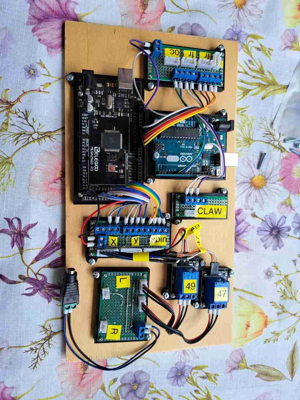
- Controlling-Boards: Arduino Uno & Arduino Mega
- Claw Model: Thingiverse: servo robotic claw
The idea was born while working on the meanwhile abandoned project “pinball-machine”. Continuing to work on a 3+ year old project base seemed no longer like a good idea. My manufacturing capabilities and process-standards evolved a lot during these years, while doing various other projects. Notably the “smart-home/security” project, which kicked off my production of homebrew parts through 3d-printing and evolved the planning & execution of electrical components.
So it became clear that the “pinball-machine” wouldn’t be wise to continue, with the realization that i would need to rework all components to fit my self-obliged production-standards.
While disassembling the “pinball-machine” i only got more reassured that i was on the right track. More and more pfusch came to light, which i had completely forgotten about. Nobody likes low-level pfusch anyways!
The first prototypes were designed and printed the very same night. As with any good project you typically want to kick off things with at least some sort of partial prototyping success, which was achieved in the following days.
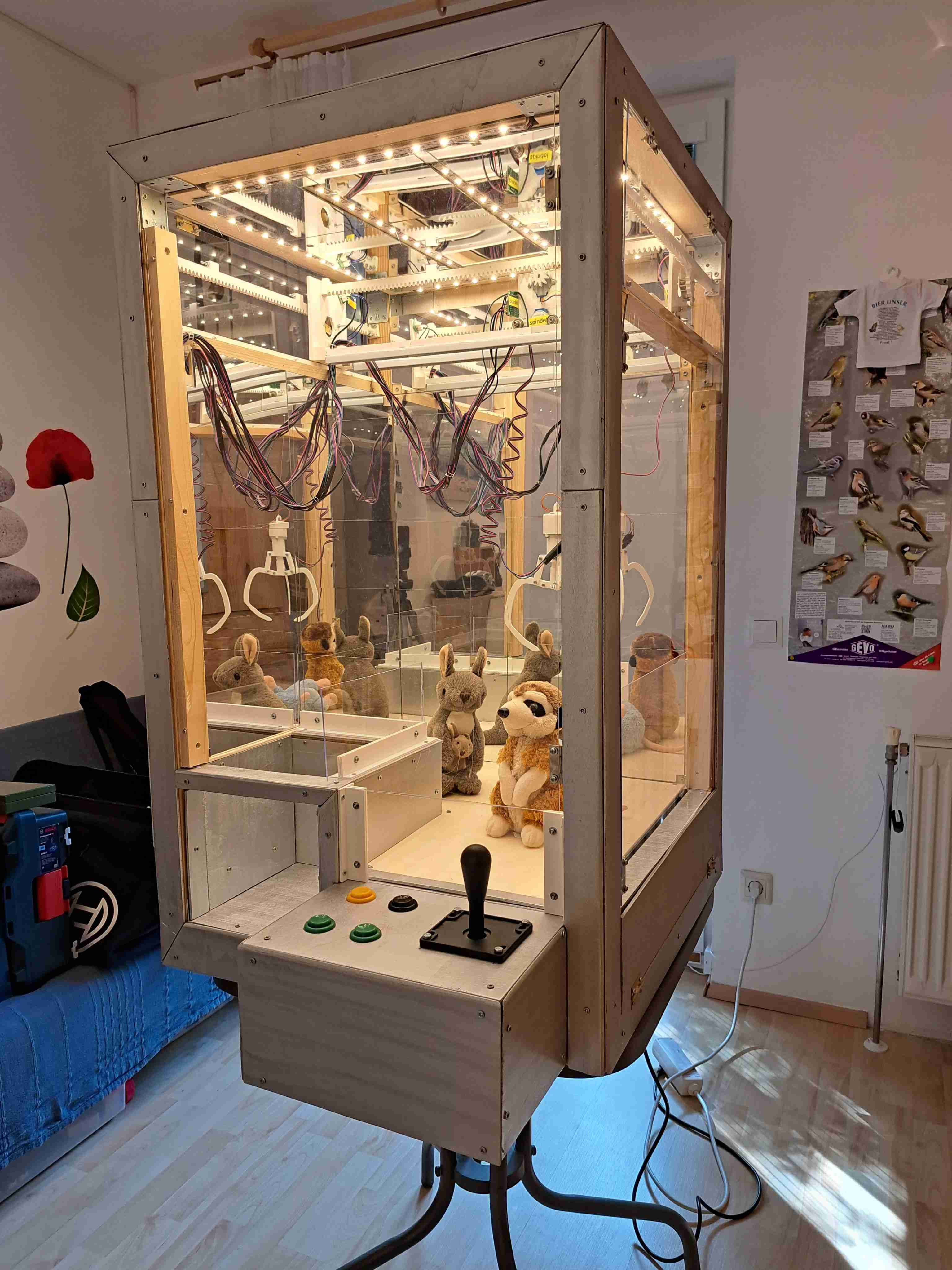
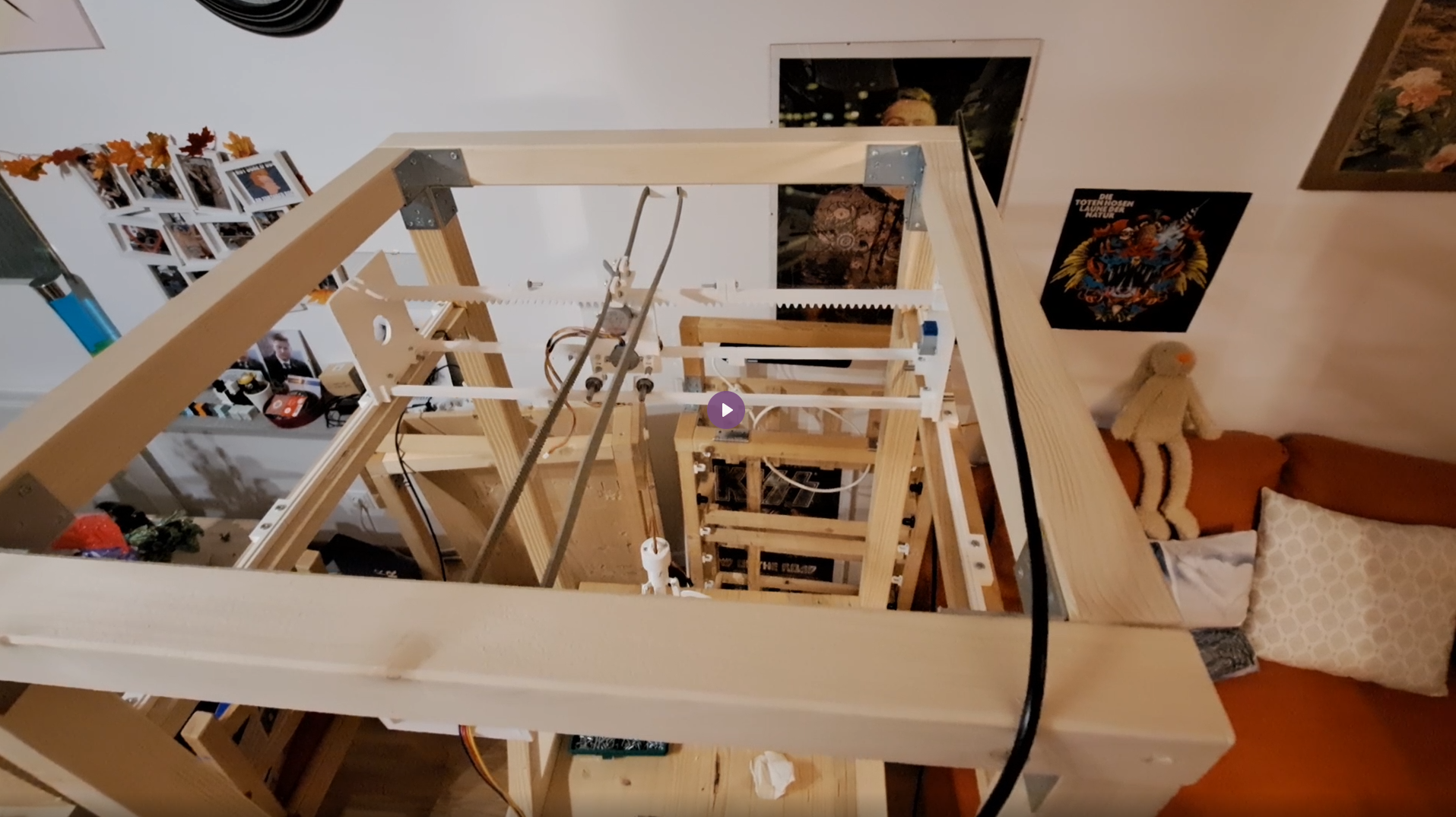
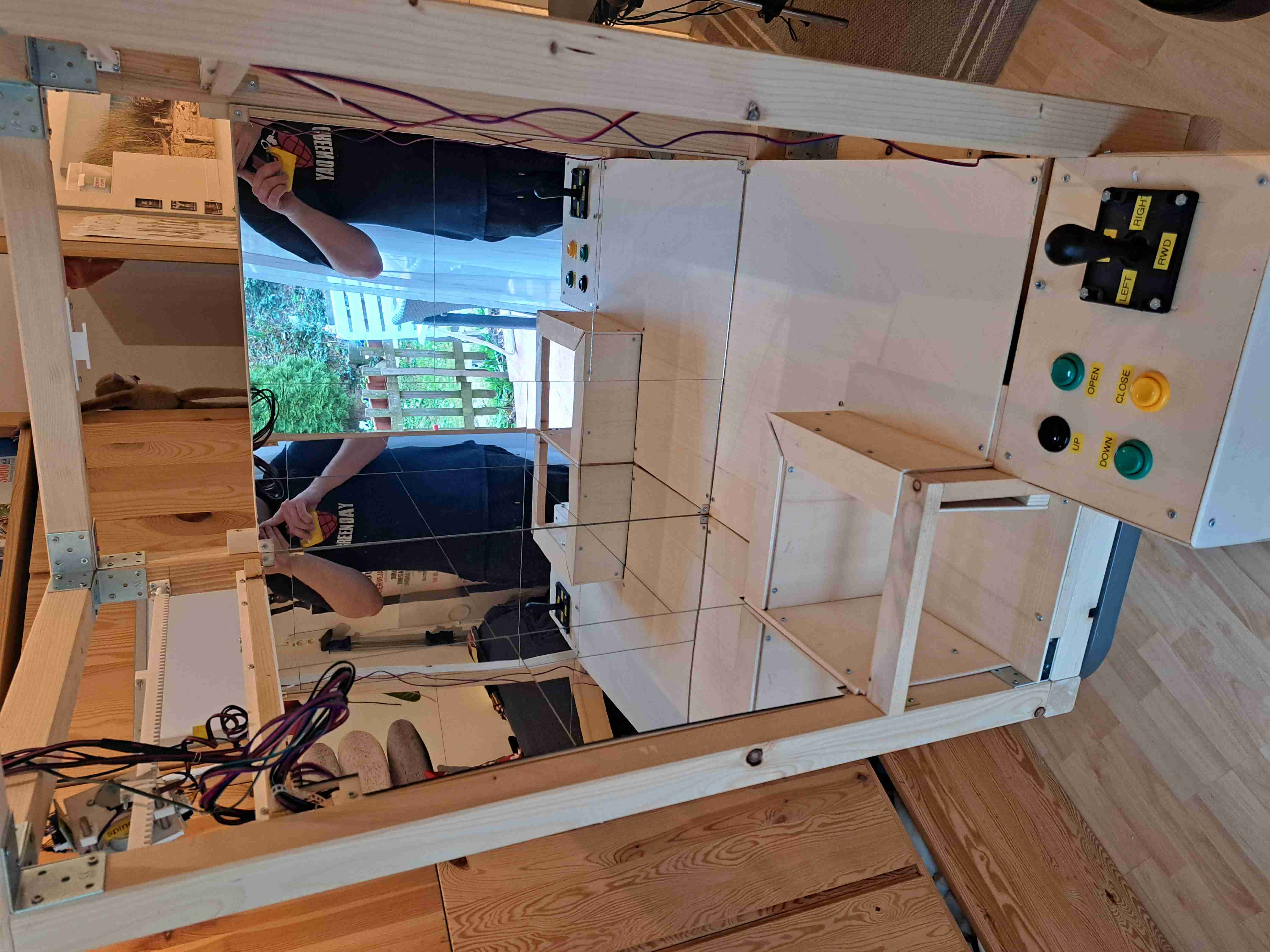
With a 60x60cm wide base-structure and 100cm in height, there is approx. 60cm of total claw-travel left for the player to be utilized.
The claw is the only part of the whole assembly which is from an external source. (see key-facts table on top)
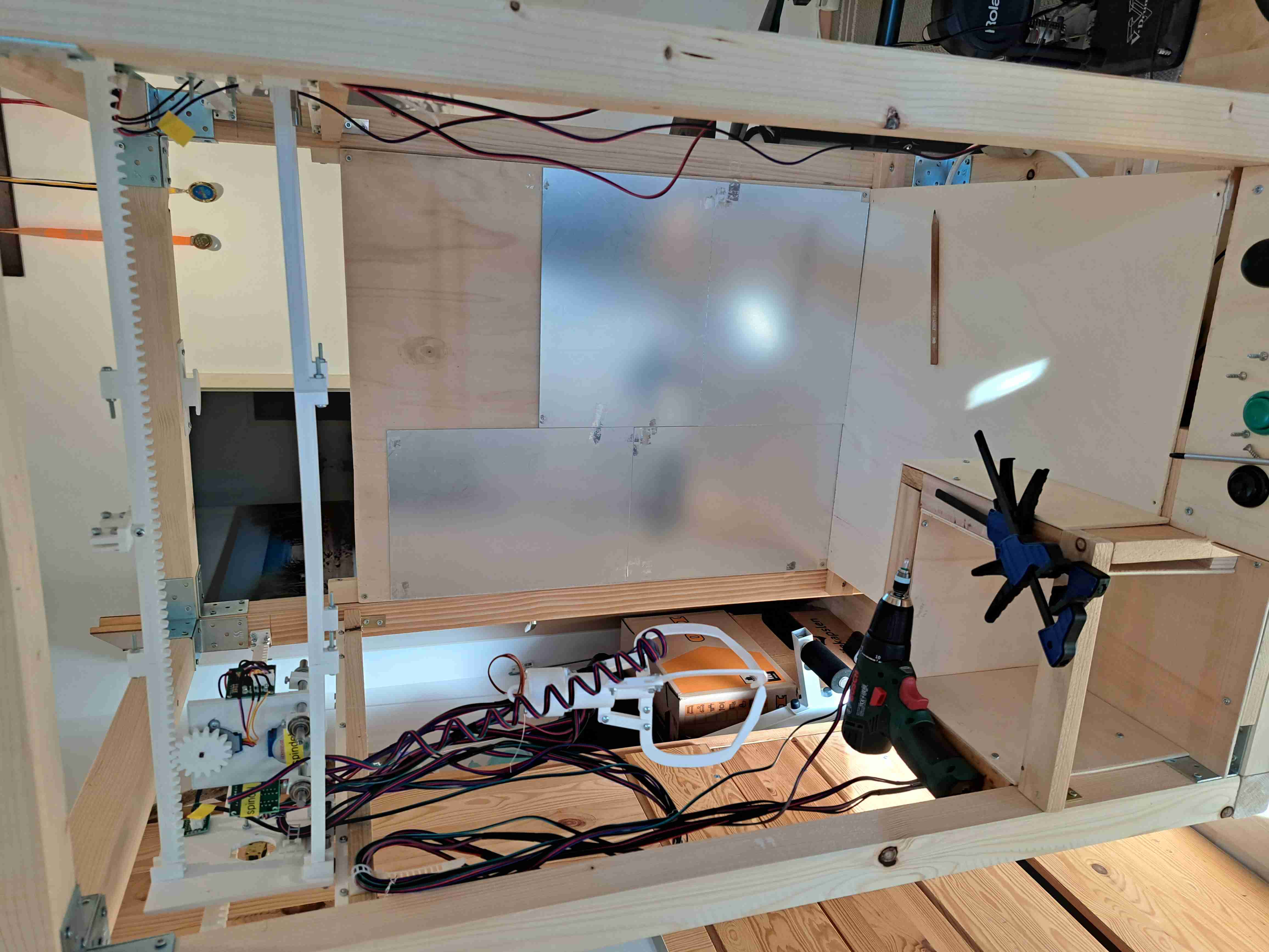
Given the clear goal of not using Off-The-Shelf Assemblies like seen on several maker-markets, i needed to come up with a two-axis gantry, which can move the spindle, the claw and its content.

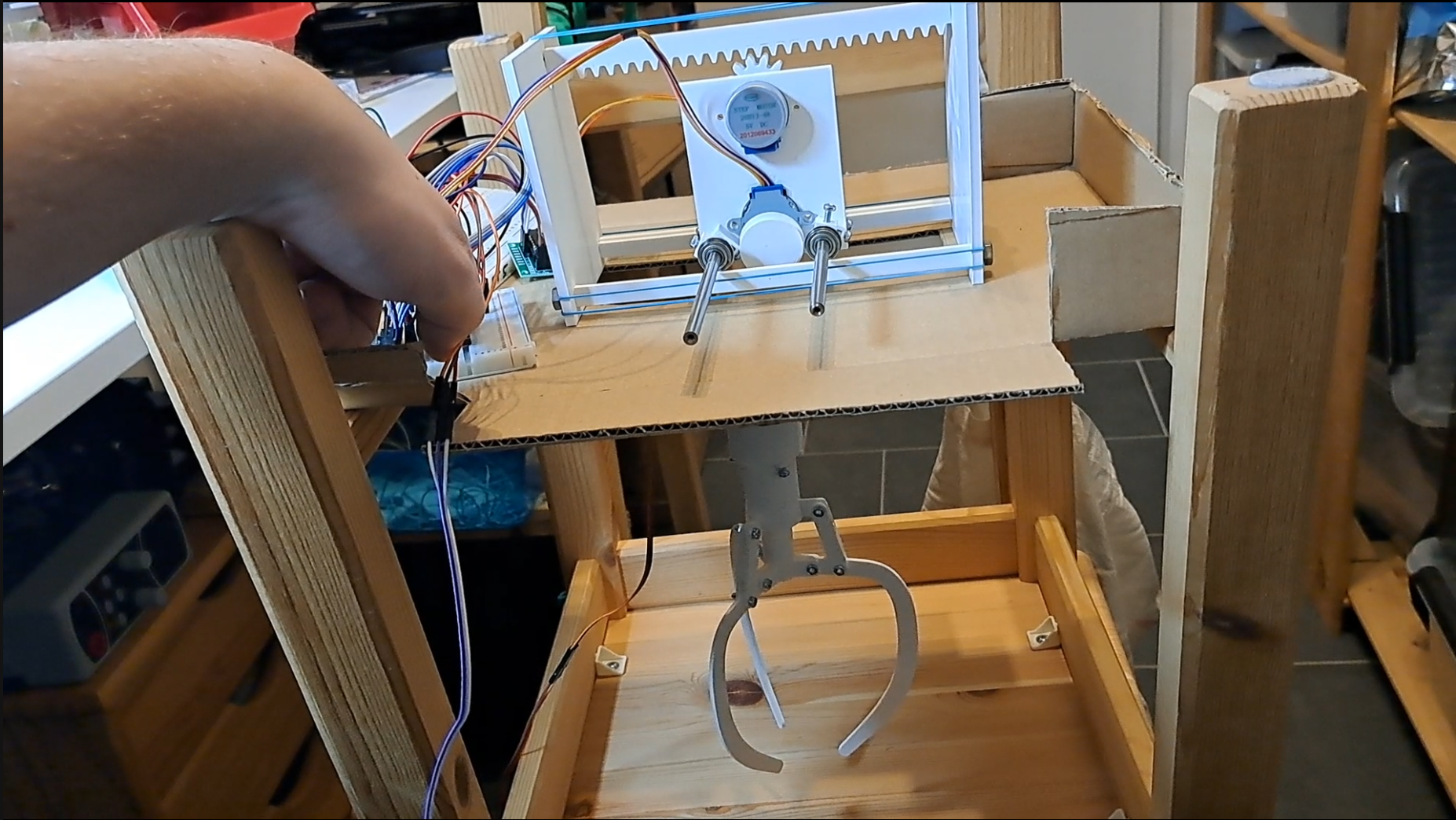

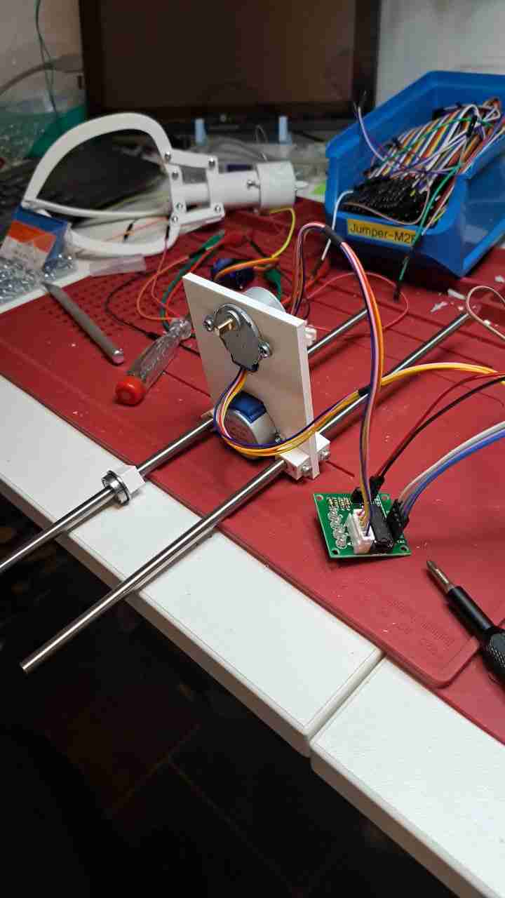
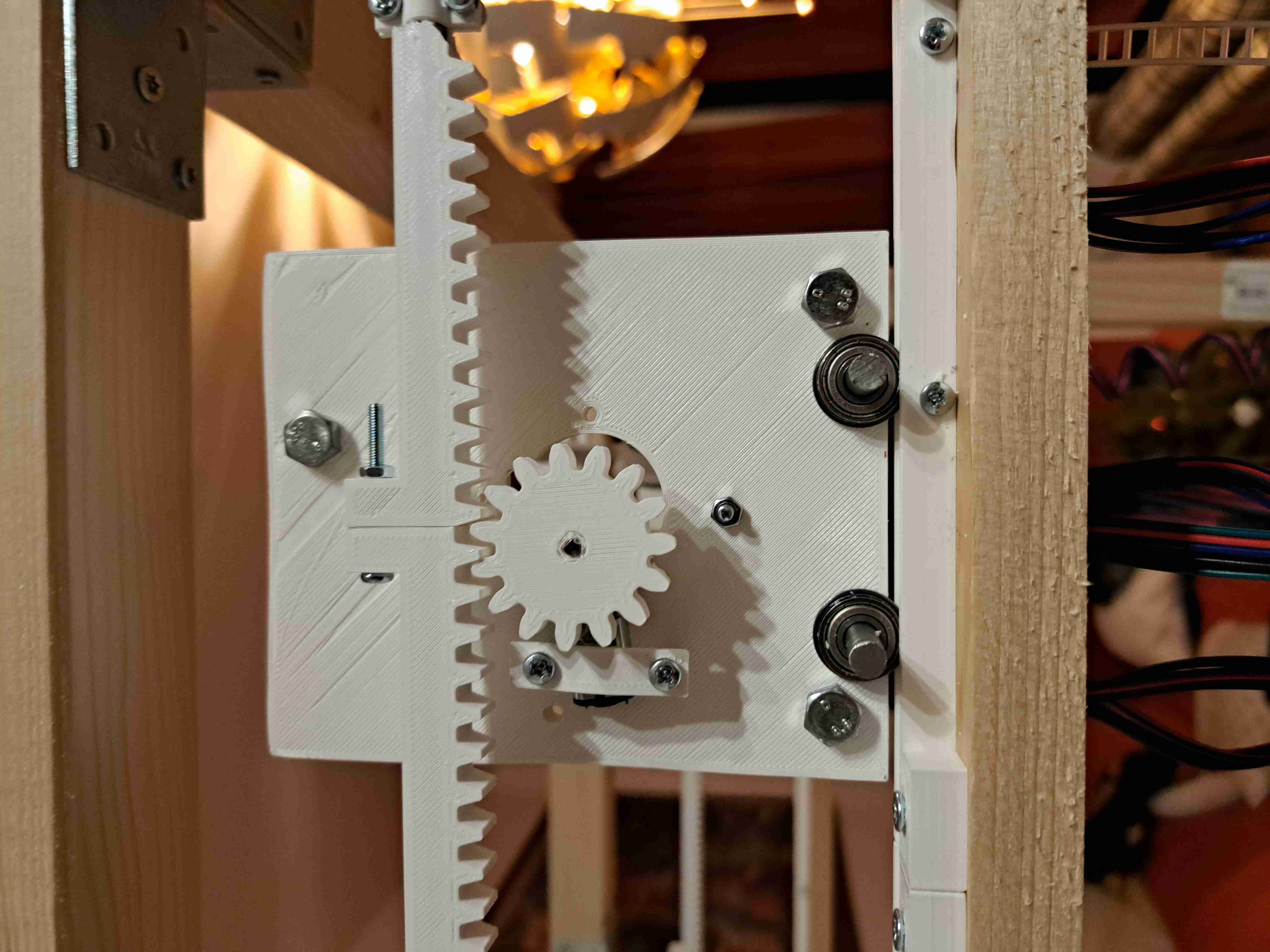
The spindle was an easy task. It is made up of a 28BYJ-48 stepper-motor and a disk with an indentation in the center. A Fishing line is attached to the through-hole in the spindel-disk. The other end of the fishing line gets tied to the Claw-Assembly.
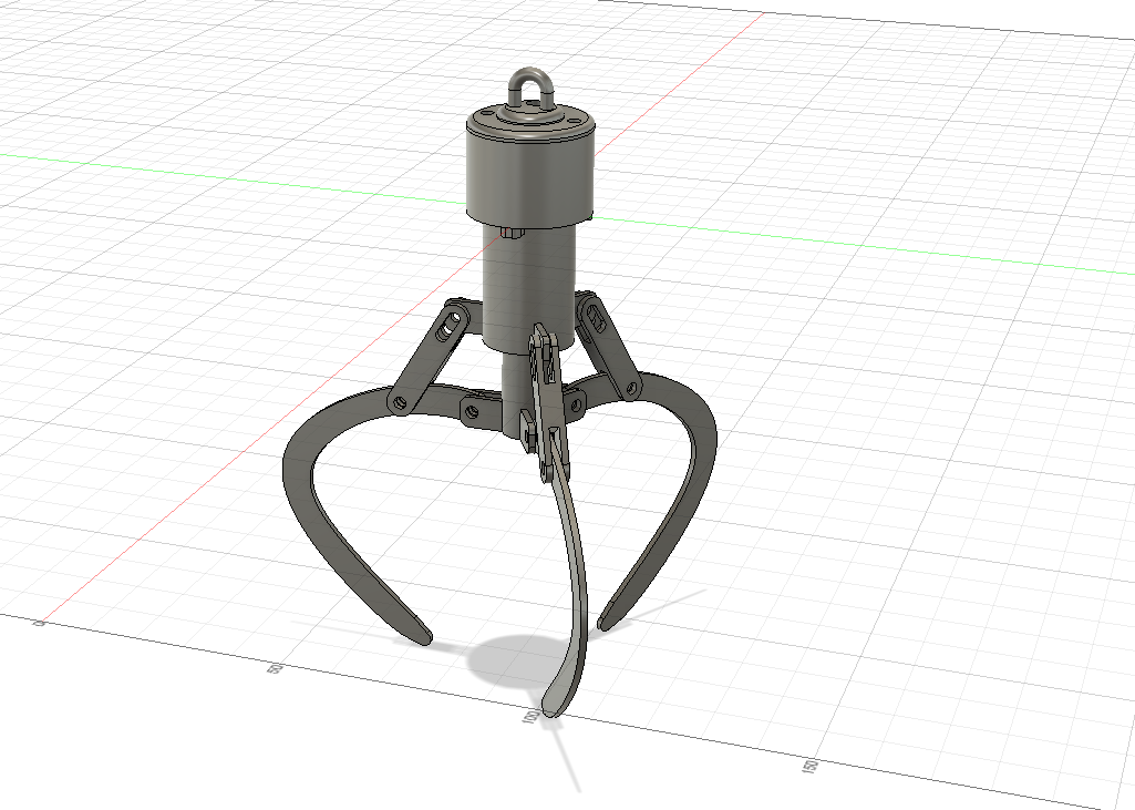
Picture Credit: Cynahsy @ Thingiverse
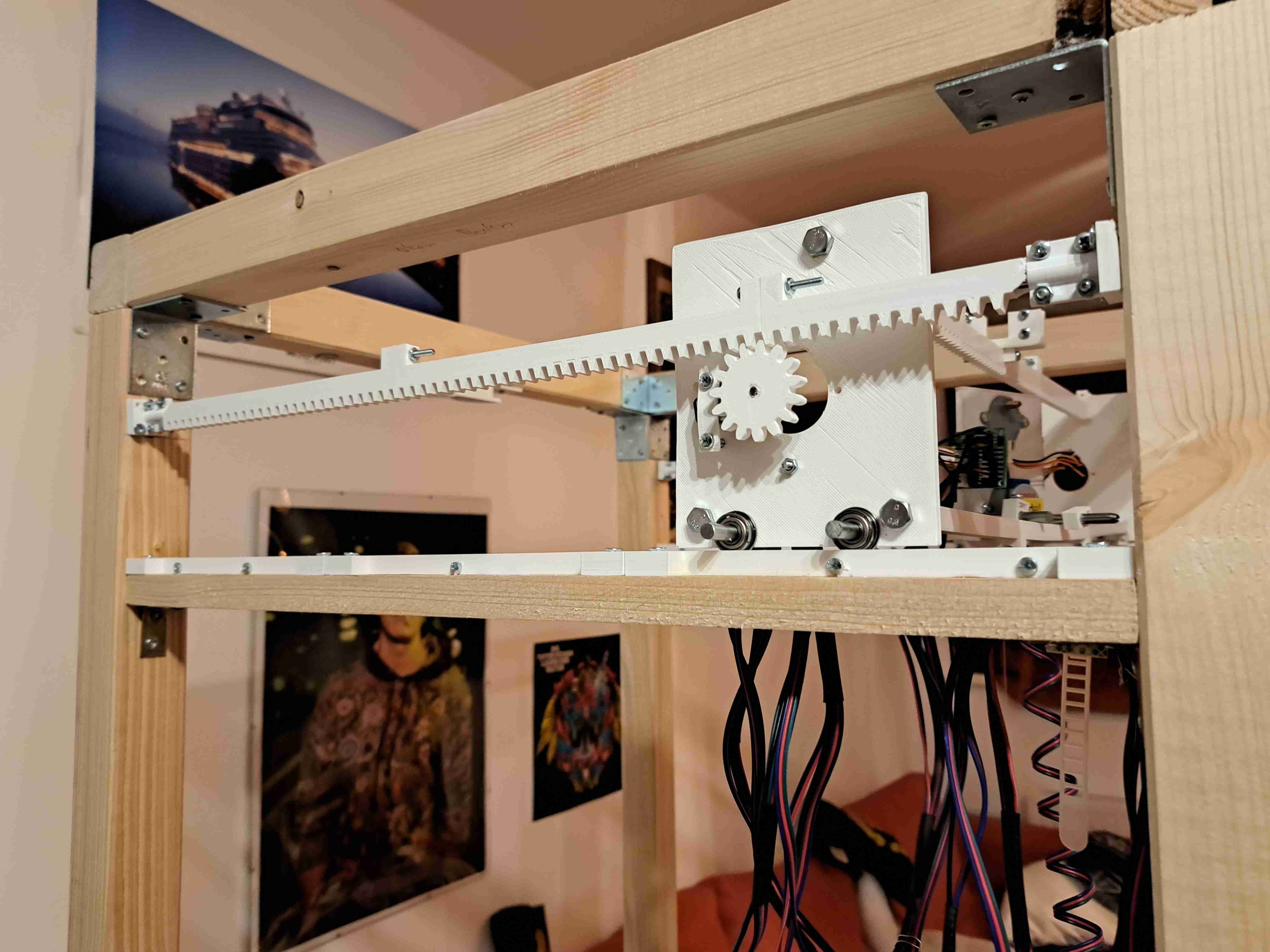
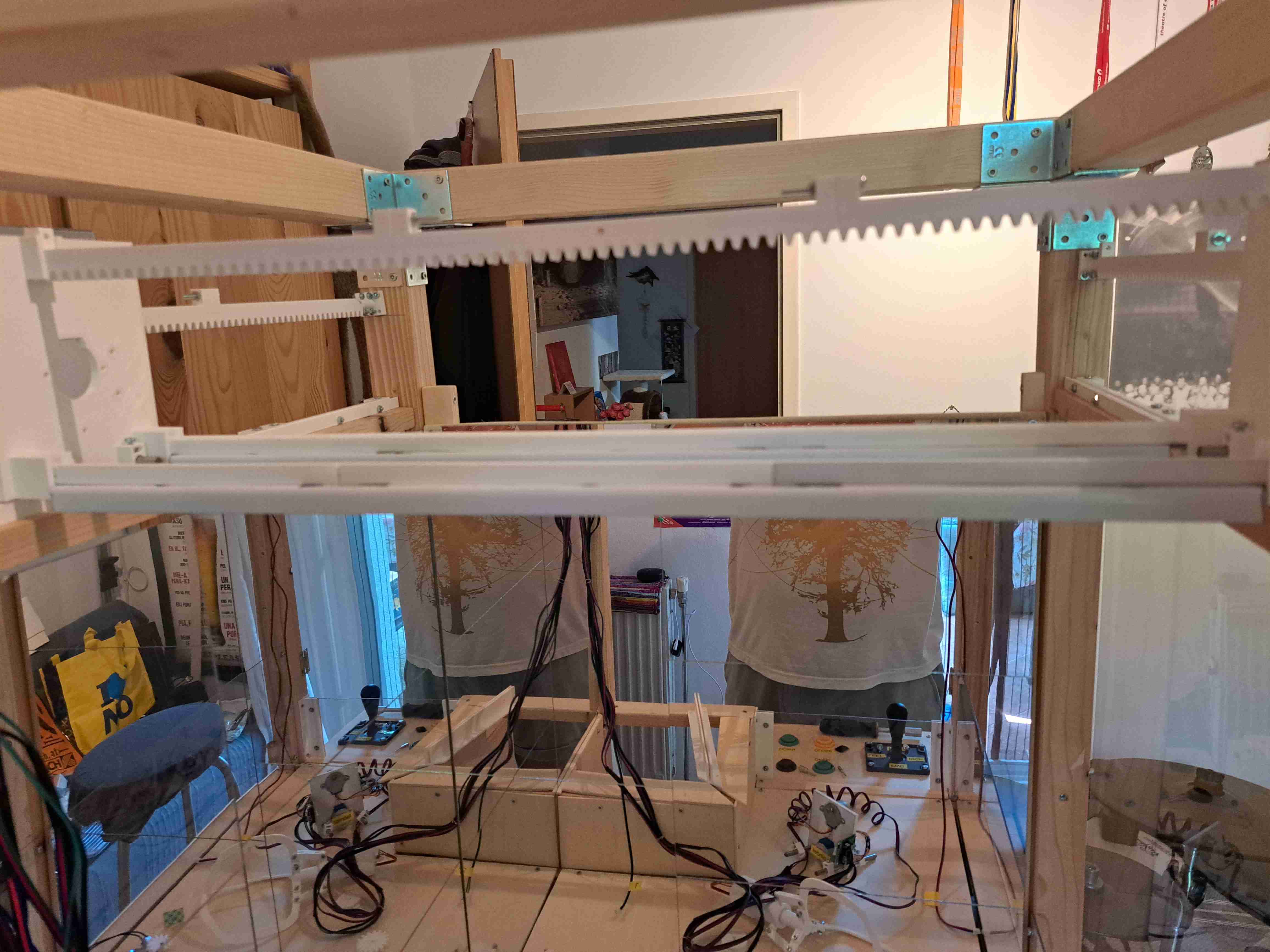
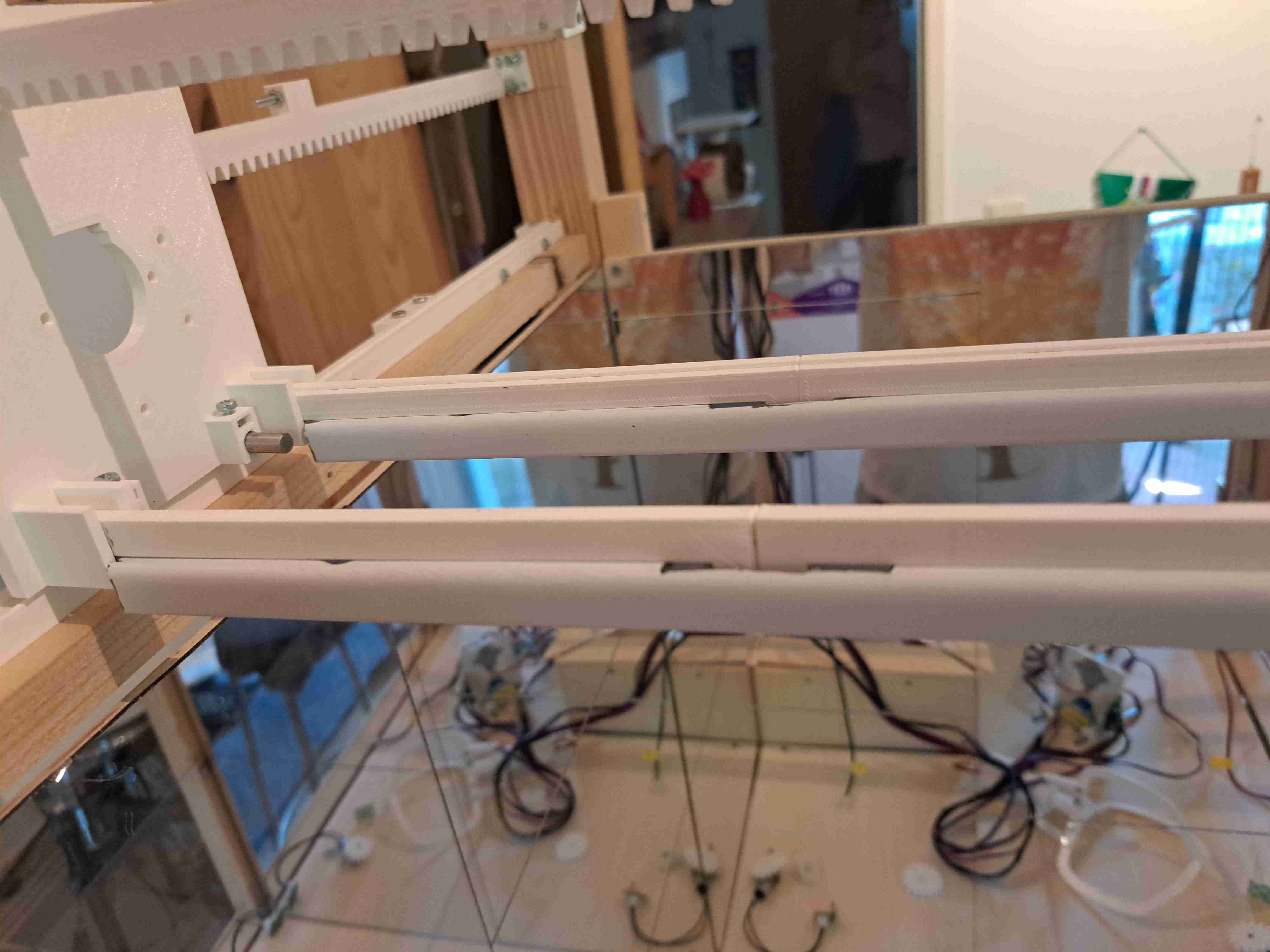
Movement along the Y-Axis was pretty straight-forward. The Baseplate holding the Spindle-motor got 2 metal rods fitted to its bottom, with ball-bearings on their ends. Those bearings are riding on parallel tracks, allowing the gantry to move freely. A pinion-gear got mounted to the top of the Baseplate, which rides along a gear-rack at the very top of the gantry. Various iterations of this gantry lead to the final design, which is made up of several rail-parts, fitted together with metal rods on the inside. M6-Screws hold the rack & rails on to the side-plates and provide stiffness.
Basic Movement along on the X-Axis wasn’t as straight forward. The fact that ball-bearings riding on tracks worked so well, paved the way to recreating this as the basics here as well. Many tests got conducted as to how the whole Y-Gantry could be moved without major skewing. The first idea, with using a rack and pinion gear got eventually thrown out. It wasn’t feasible to turn two 28BYJ-48 stepper-motors at the same time off the same Arduino controller. At this point in time, these motors were all i had at hand, so i tried to get it to work somehow. I got inspired by the belt-driven designs that bed-slinger 3d printers use for their heated beds. A belt gets tied to both ends of the heated bed, gets wrapped around a pulley and stretched around a powerful stepper motor. With an old belt i had lying around, i tried to recreate this functionality.


The 28BYJ-48 stepper-motor was able to move the gantry at first, all be it with a lot of skewing involved. I tried to work that out with guiding rails and different belt tightness etc. but the little stepper motor showed its demise when a payload got attached to the spindle. It couldnt handle the weight of anything more than a peanut really.
All in all it became clear that i had to find a more powerful motor for this task. I first tried to use a beefy stepper motor, which was lying around in my random parts bin. I wasn’t able to track down any meaningful documentation on which voltage and controlling circuits it was expecting, so i quickly abandoned it. I found a dc-motor on amazon which had different gear-ratios available. It was primarily used for RC-Cars, so i gave it a shot in my belt driven design.
Even though that didn’t work out as planned, i now had motors on hand which only required a closed 12v dc-circuit to run. With a couple of relays i could switch the circuit direction and change the motor direction. And the best part of it all: you could hook up as many motors to the 12v psu as you like! (as long as the provided wattage was enough of course)
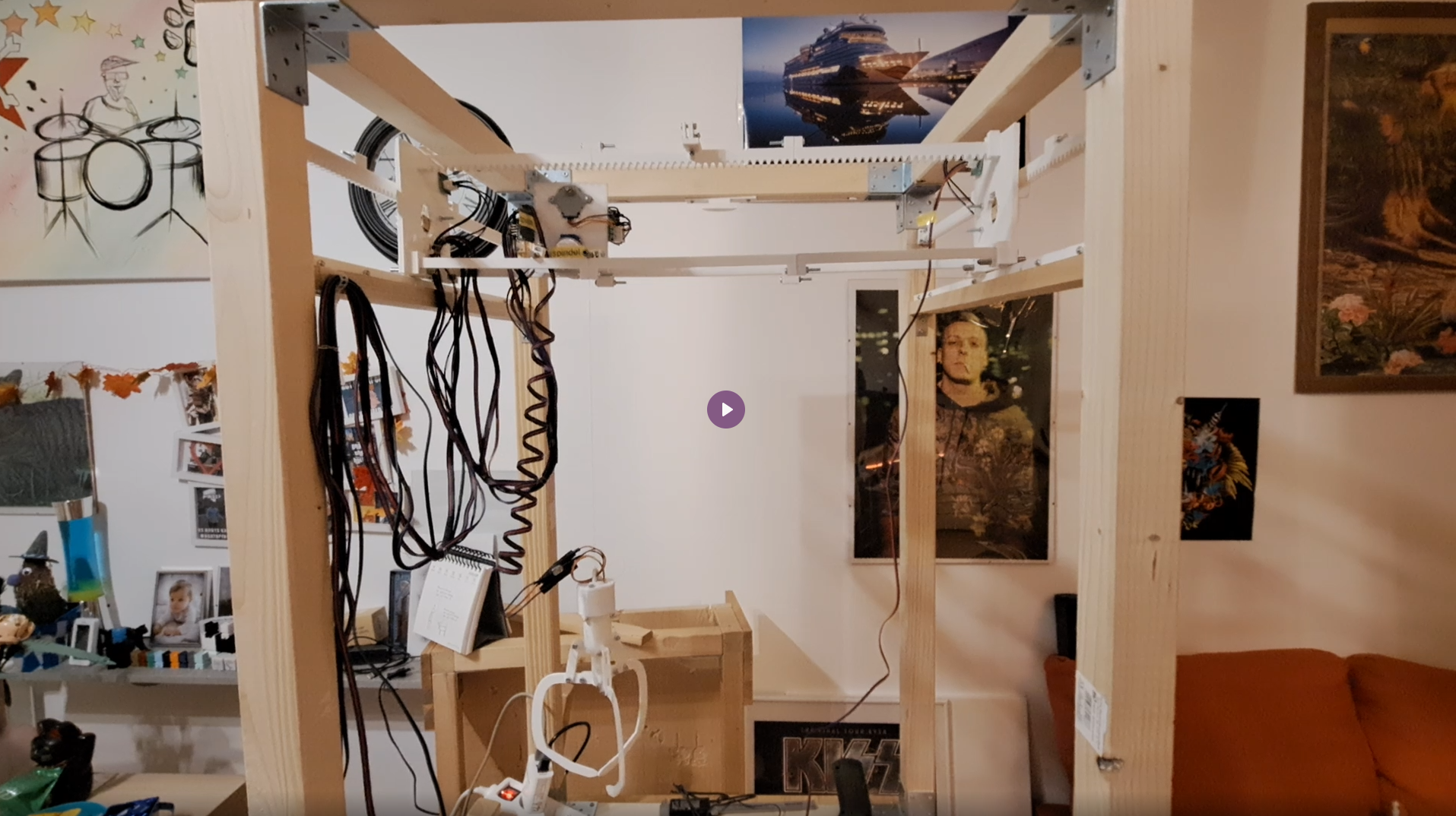
This meant i had a way of controlling two motors at the exact same time with a minimum amount of inputs, without worrying about timing and possible offsets. Each side-plate of the y-gantry got fitted with a dc-motor and a pinion-gear. Alongside the movement rails gear-racks got installed as well. the Movement along the X-Axis was done!
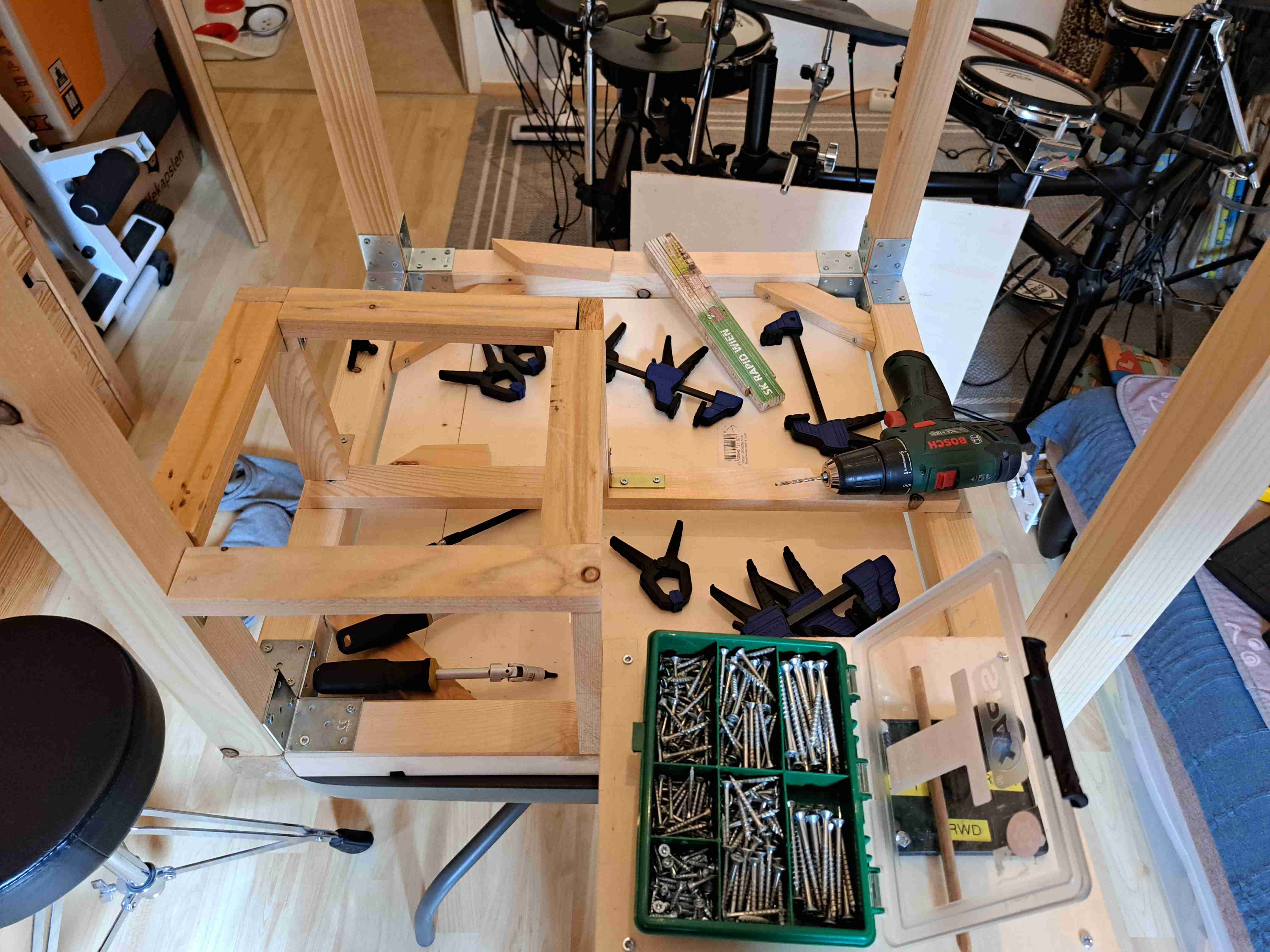
Construction of the Wooden Structure happened alongside the electrical and mechanical stuff. Once the rough dimensions for the controlling console and the price-bay were set, each got their own framing and paneling done. Since most of the underlying framing wouldn’t be visible at all, i didn’t care too much about doing a beautiful wood-working job.
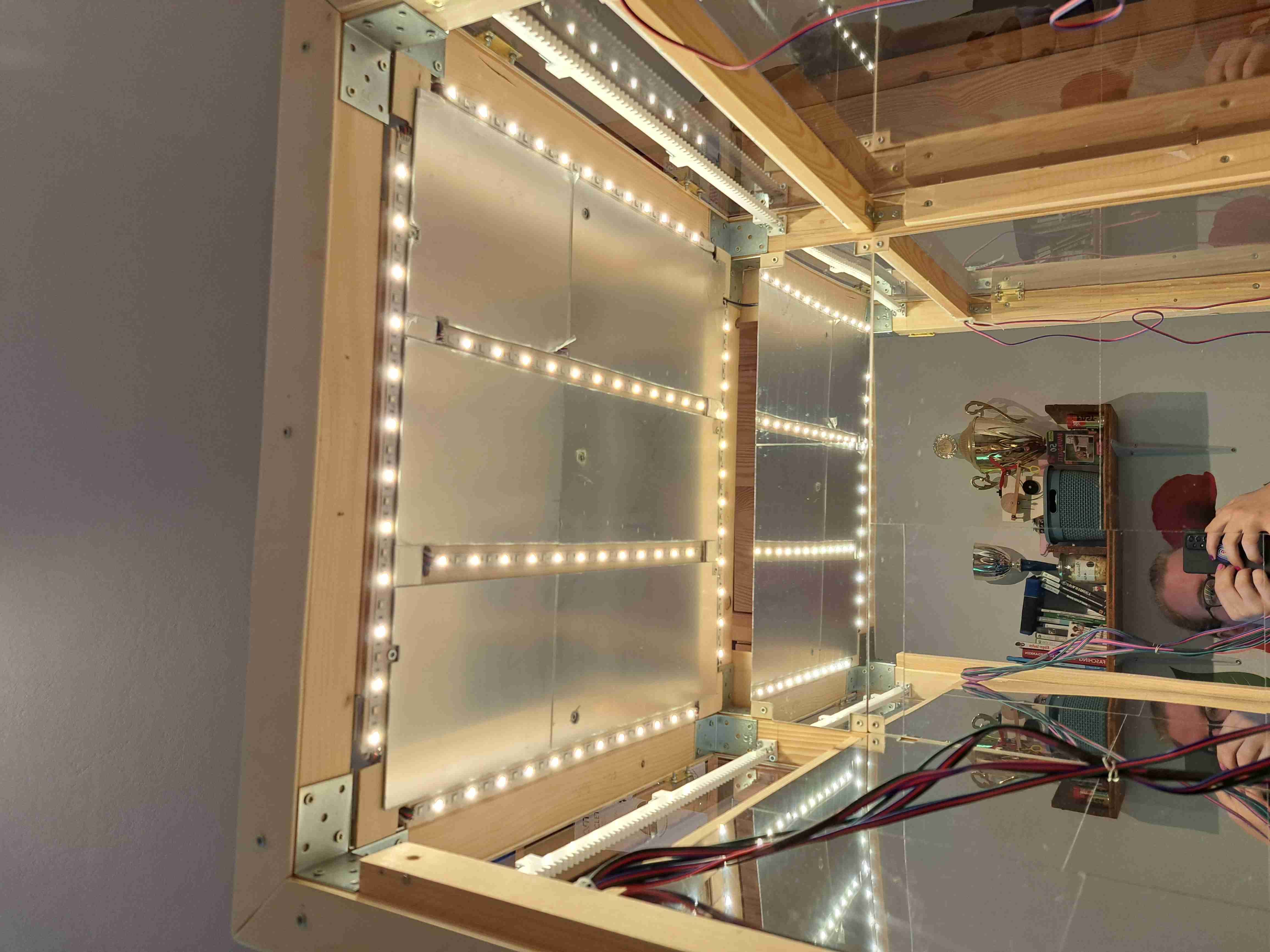
I decided to try and go for an industrial/metallic look, which would mimic those claw-machines seen on fairs. With that in mind, the front & right side of the playing field would need to be see-through, the other adjacent sides should have some kind of mirror to give the illusion of depth.
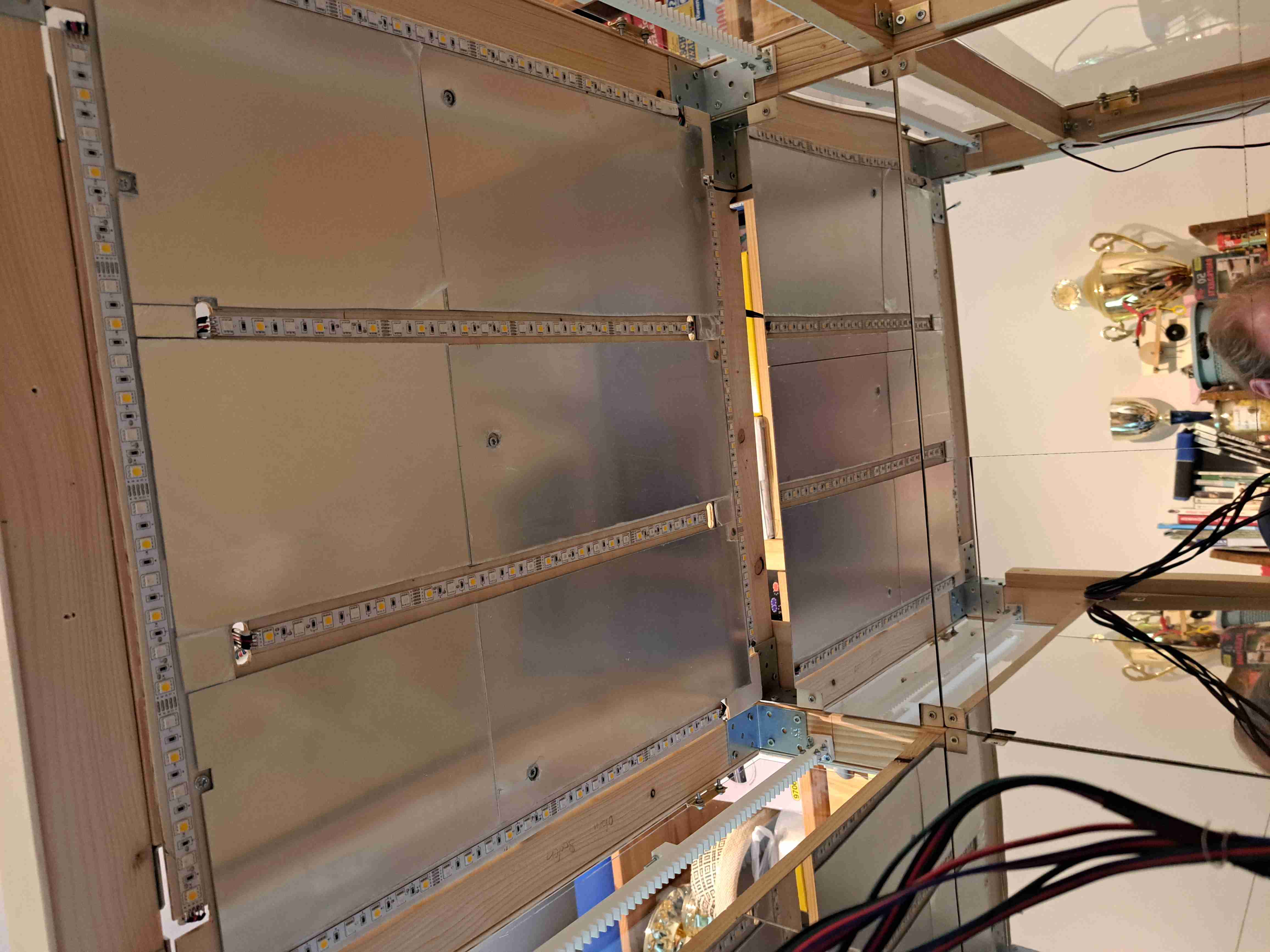
A4-shaped mirror-tiles which i found on amazon did the trick. They were very easy to cut and came with adhesive pads. I had to reorder them several times, since i later chose to lay out those tiles on the ceiling panel as well.
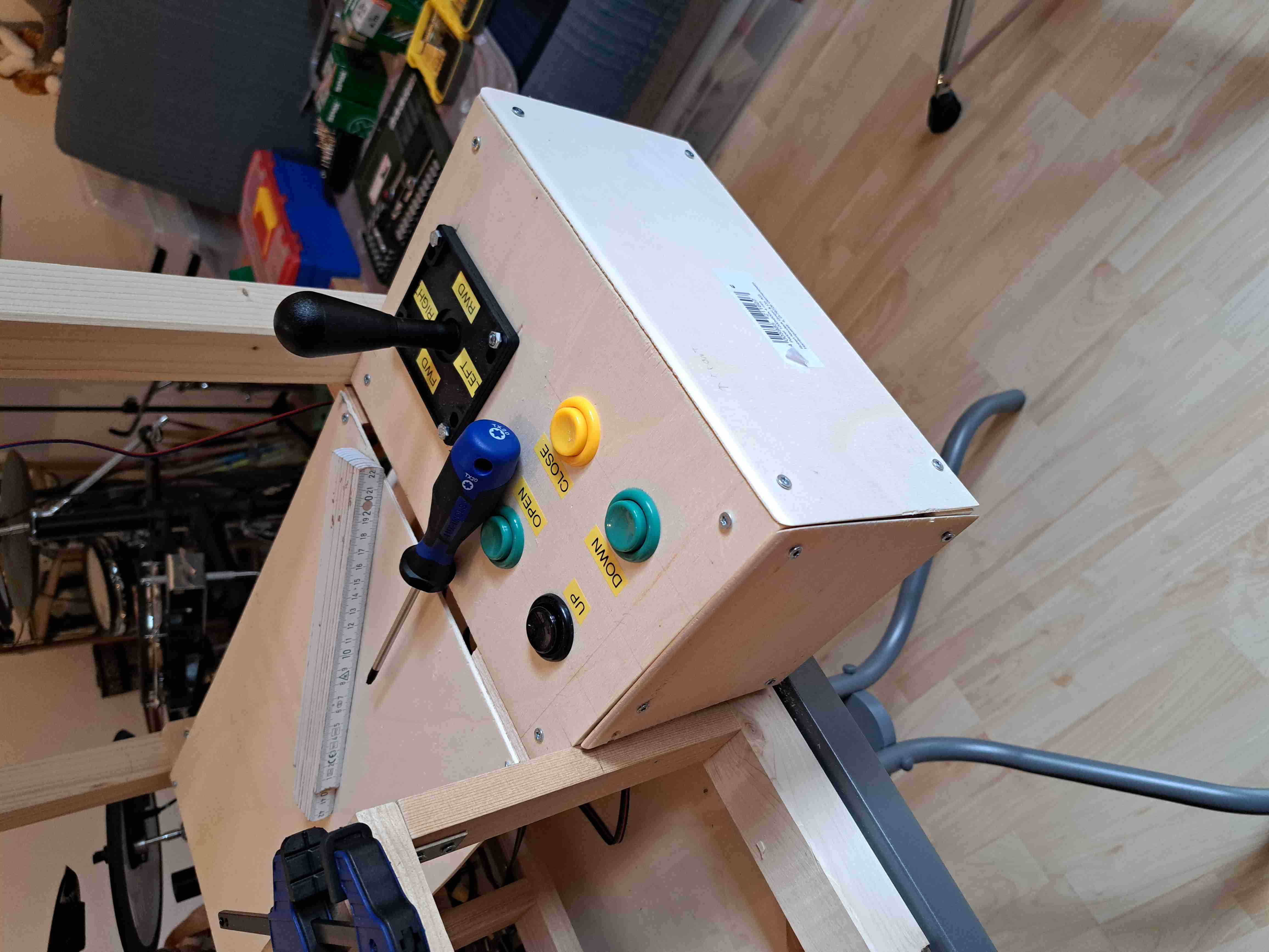
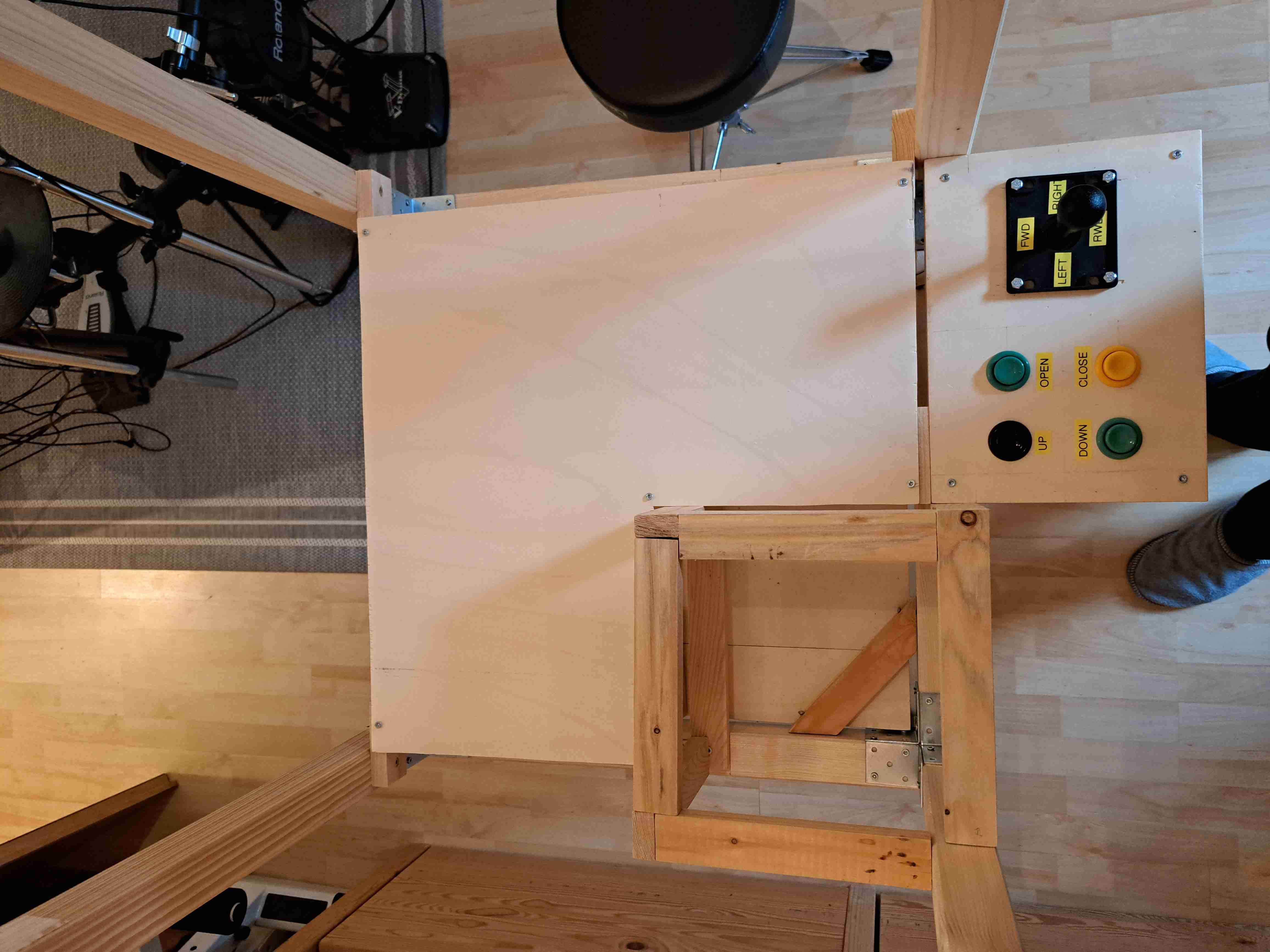
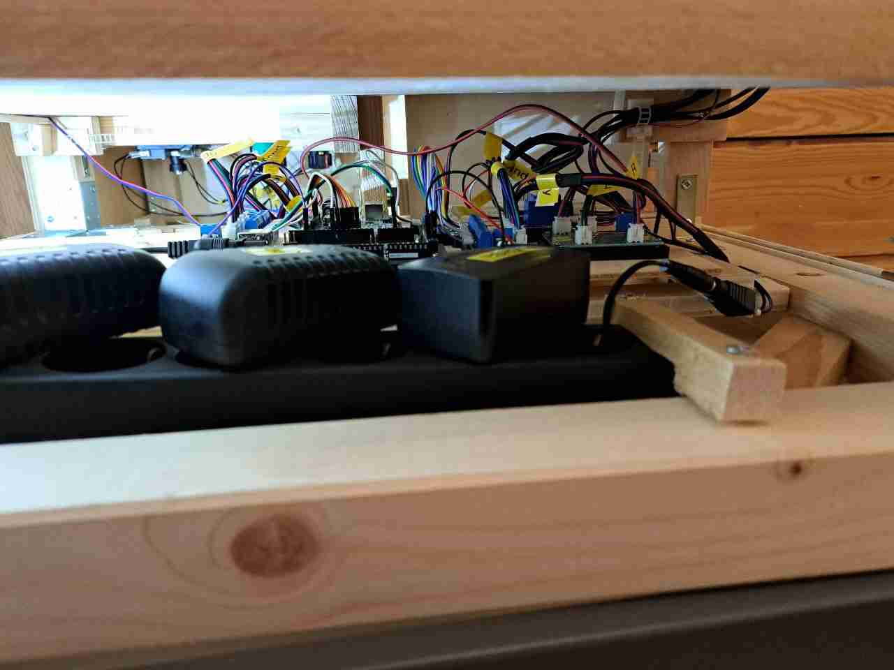
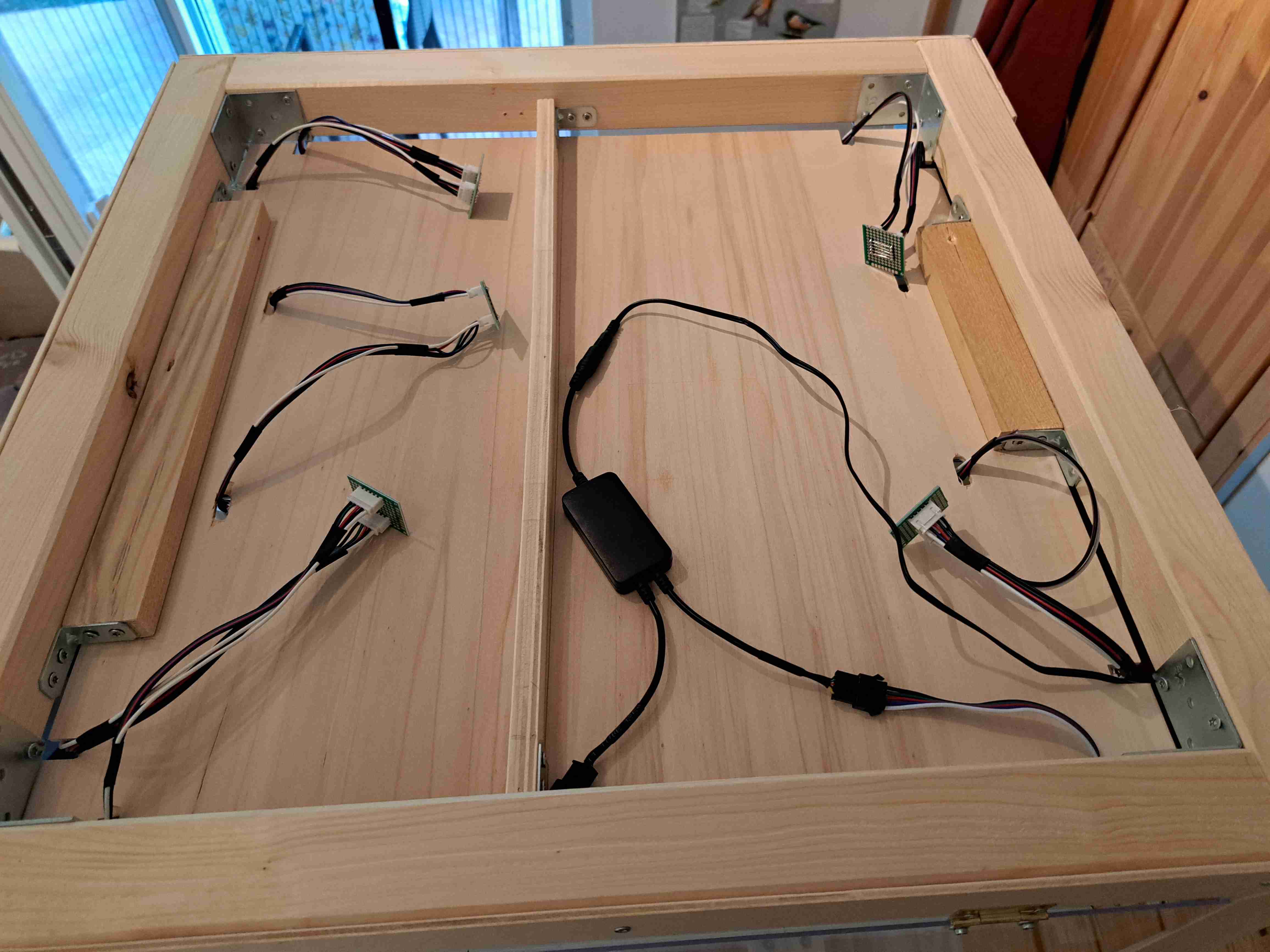
Cable-Management and mounting the two arduinos and their accompanying PCBs turned out to be quite a hassle. The most-bottom layer was partly used up by the price-bay, which made it difficult to properly fit the power-strips, make clear wire-paths that would only cross the least amount necessary and still be accessible for maintenance. By installing another layer which would hold the PCBs and Arduinos i managed to make room for the PSUs to be disconnected without having anything in its way.
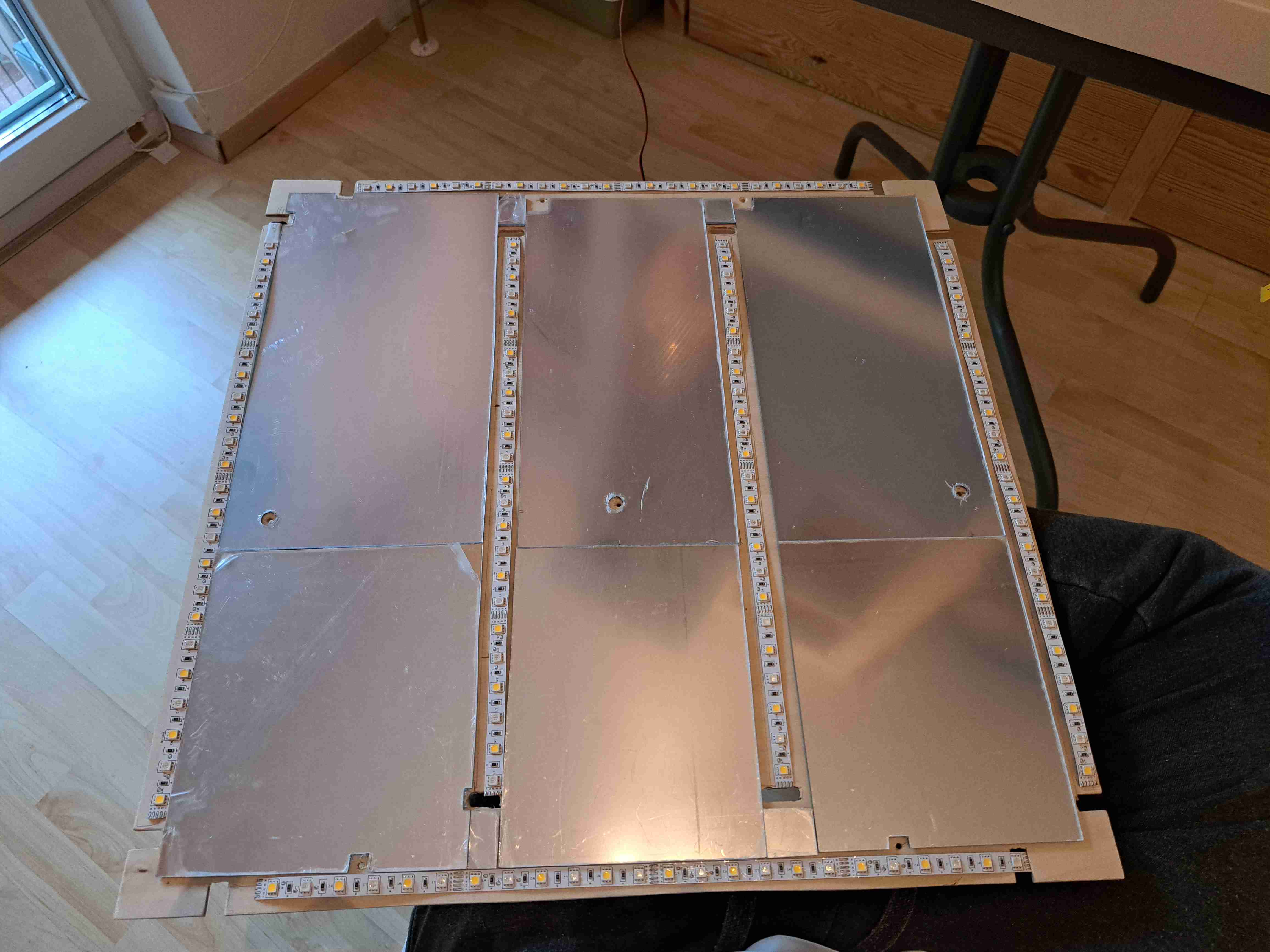
The Ceiling shares its space between the before-mentioned mirror-plates and LED-stripes with dedicated warm-white LEDs. The “Magic Home” LED-Controller is very handy for situations like these. Its integrated WIFI & App-Connectivity makes it possible to mount it hidden anywhere inside without the IR-Receiver being visible. Even Though it only gets changed very rarely, its nice to have the ability.
A soon-to-be long-lasting problem showed itself once all the Gantries & main Mechanics were installed. The Claw had no Problem lifting the stuffed animals and transport them anywhere it got demanded to. But the added weight & lever force from pulling a load introduced a bend to the Y-Gantry Rails which i had not seen before. Even though i joined the 3 pieces of Rail with overlapping 6mm Metal-Rods, the unsupported sections were able to bend quite a lot. Unfortunately, the bend in the Rails introduced a growing gap between pinion gear and its Rack, leading to a free running gear on the most bent sections. I tried to counter this problem, by making the pinion-gear bigger as needed, but the bending continued to happen. After iterating the fourth time i knew i had to find another solution.
I landed on using a C-Section Metal bar, which the Rails would sit on. Some modifications with the Dremel-Tool and Sandpaper were needed. This stopped the bending entirely. TIL: Using Metal can be quite fun, when using appropriate power-tools. (What a shock, i know)
Another Problem which only got visible over time was the method for mounting the X-Axis DC-Motors. The 3d-printed mounting plates would lose its strength over time and let the motors lose their angle of attack. Two simple Plywood Plates were cut as a replacement, which worked fine for the time being. Future-Coni-Here: I still need to design a mount for the Motors to rest upon. The Plywood Plates can not hold enough force on their own. Maybe i should add that to my To-Do…
The most tedious Process started around May, which meant i was near the completion of the project. Cutting all the Plywood-Plates which make up the outer-shell of the Framing was a lengthy process. One Weekend i concentrated on “measure twice, cut once” which meant i would work very precisely. The next week i would turn the process upside down, and focused on “measure once, cut twice”. Both approaches ended up using the same amount of time, interestingly. We won’t talk about Project Cost at this stage ;-)
As the final step was coming closer i was looking for a way to paint the outer panels.
I wanted to try spray paint, because i had made rather poor memories from working wood-paint on the arcade-machine.
I settled on the “Edding Spray Paint” - Silver Color - a not so cheap can of spray paint which holds not so much spray paint.
With the Pack of different sized Spray-Heads i was off painting. Making sure not to paint my lungs and eyes, wearing protective gear was never a question. The Results of Painting the first tryouts were very promising, so i created a daily routine. Coming home from work - spraying a new layer of paint - jumping into the pool - repeat.
Each Piece got 3 Layers of Coat on its topside and one light layer on its bottom, making sure to cover the edges properly.
As well as being one of the lengthiest parts of this project, it was also the single most expensive one, with using over 10 cans of spray paint.
I will definitely look into other brands of spray paint next time.
Conclusion
Seeing this machine in action, friends having fun trying to catch a price, the LEDs lighting up the mirrored play-area when turning on, hearing the quiet - but still noticeable - motor-noise from the gantries and realizing: “Wow, i created this thing. All on my own. i apparently know how to do this shit! O:” is still one of the best feelings in the world.
If you have ideas for new fun prices or my next build, let me know! You can find my E-Mail here: :-)
Thanks for reading. ~Coni