A wedding gift for two very close friends. ❤️
Key Facts:
- Kick Off: 01.03.2024
- Finish: 02.06.2024
- approx. Cost: undisclosed
This project involved two major parts i had to develop.
A music player and a motor-driven carousel.
At first i tried to let one arduino control both the music and the motor.
Since i had gathered lots of experience controlling various stepper/dc motors in the past, i knew the bigger struggle would be the audio-part.
Many iterations of buying -> testing -> failing lead me down different paths of exploring sd-card modules, active amplifiers and speaker combinations and various arduino boards.
In the end i concluded it would be simpler to acquire a used mp3-player & mini-speaker, dissasemble them both and reincorporate their components into the project.
To decrease the complexity of the overall system i decided not to use any microcontrolling at all. The carousel is powered by a standalone 3v dc motor.
Power delivery for the dc-motor & mp3-player is handled by a 9v battery. While the mp3-player was originally powered by one AAA-battery, fortunately the mini-speaker had a Li-Ion battery built in.
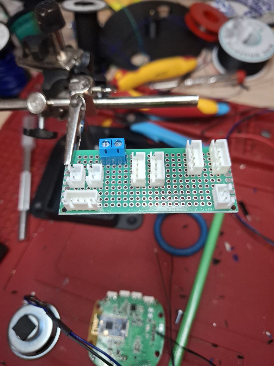
Using two buck-converters to step down the 9v to 3v & 1.2v, all the electrical components were figured out.
The design of the carousel came down to trial and error again. I really dont know how to use math for gearing and stuff (tbh i believe its black magic after all). After i figured out how to spin the figures on the carousel-board i was very pleased to see the first prototype in action.
From there on it was a lot of CAD modelling. The base of the structure is made up of the box & lid. The main box gets fitted with the inner gearing-plate.
Next, the carousel-plate and stick get screwed together and put in place on top of the gearing-plate.
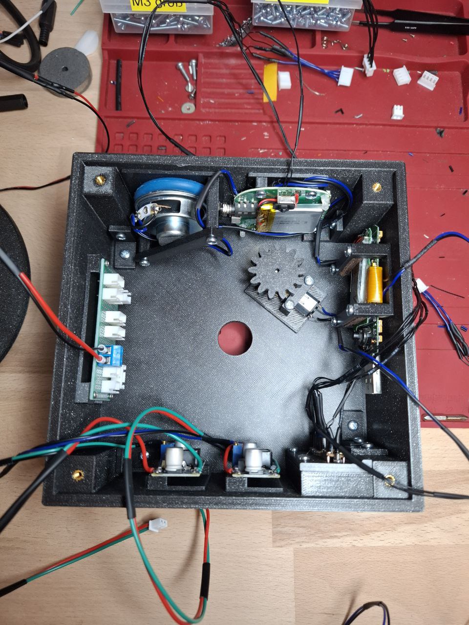
Inside the box is where the (black) magic happens.
The main gear gets screwed on to the stick and the motor-mount gets glued in place.
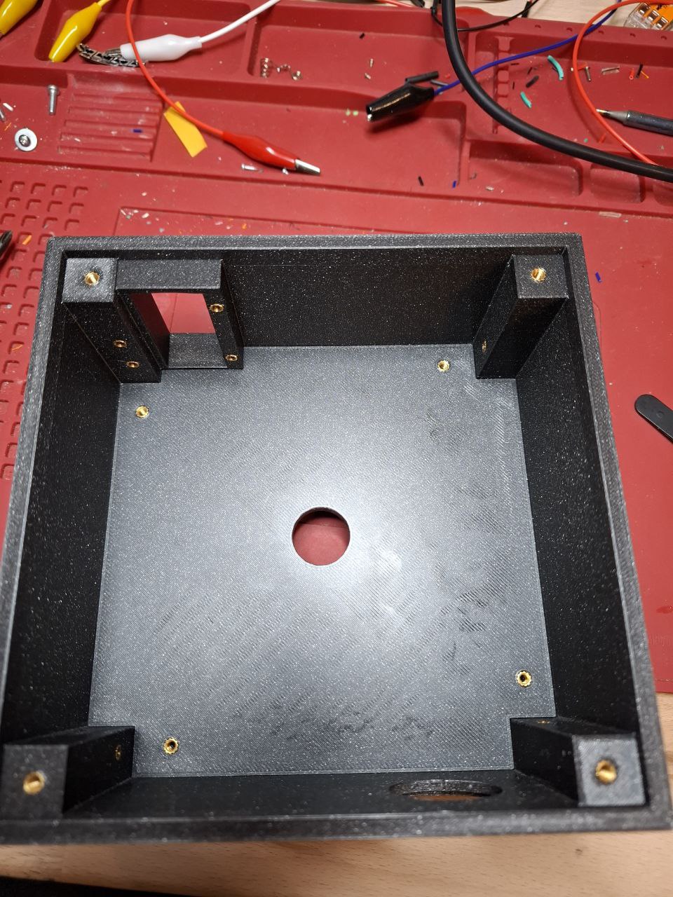
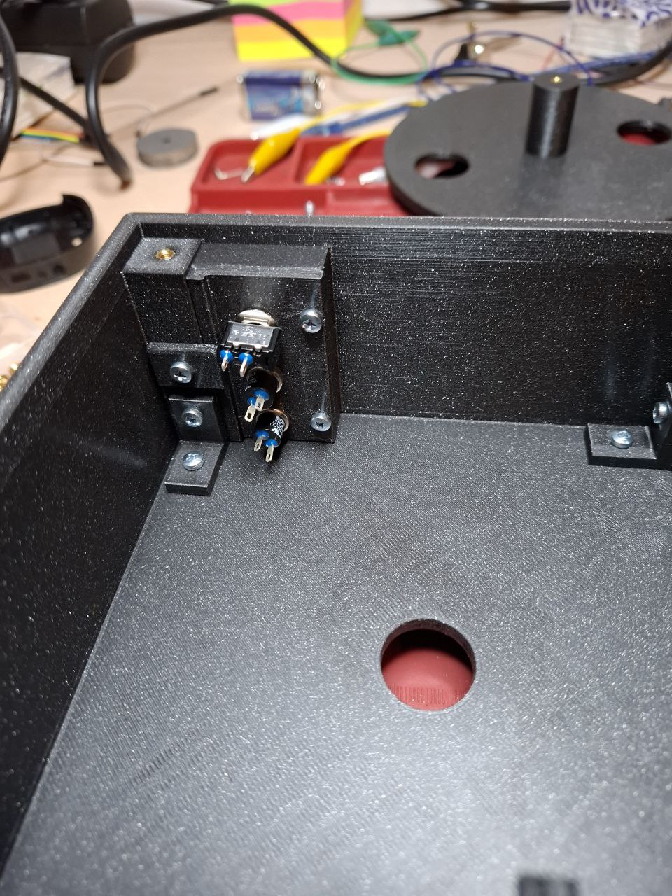
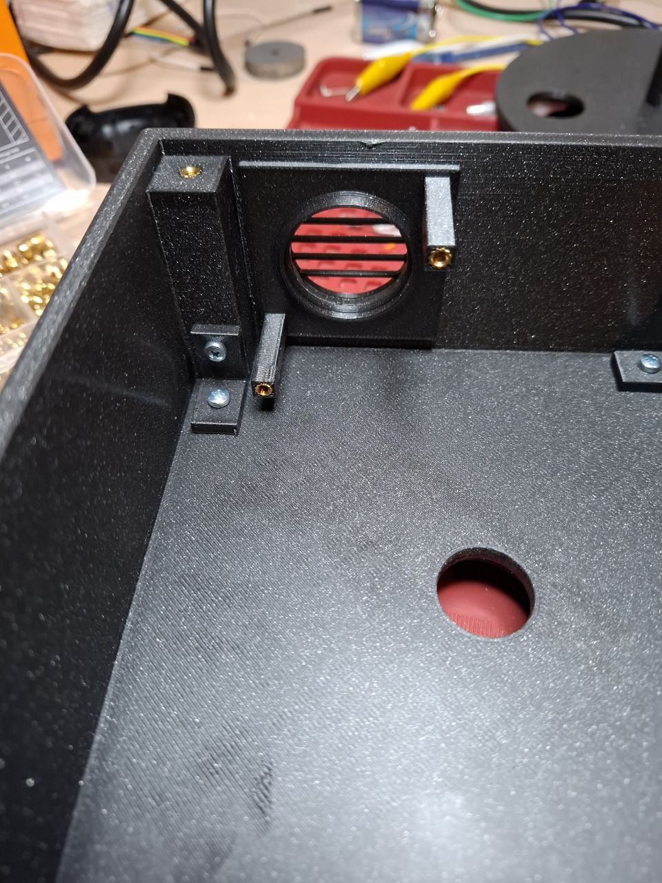

Every electrical component gets its own mounting solution. Both for ease of design and also printing stability, those were not directly incorporated into the main box-design.
Mounting the PCBs was easy enough. A plate was designed with the appropriate holes in place to screw the PCB down to. The plate then got glued on the wall of the main-box.
Everything that doesnt have holes for mounting got a top-plate, which presses the part onto the mounting-plate.
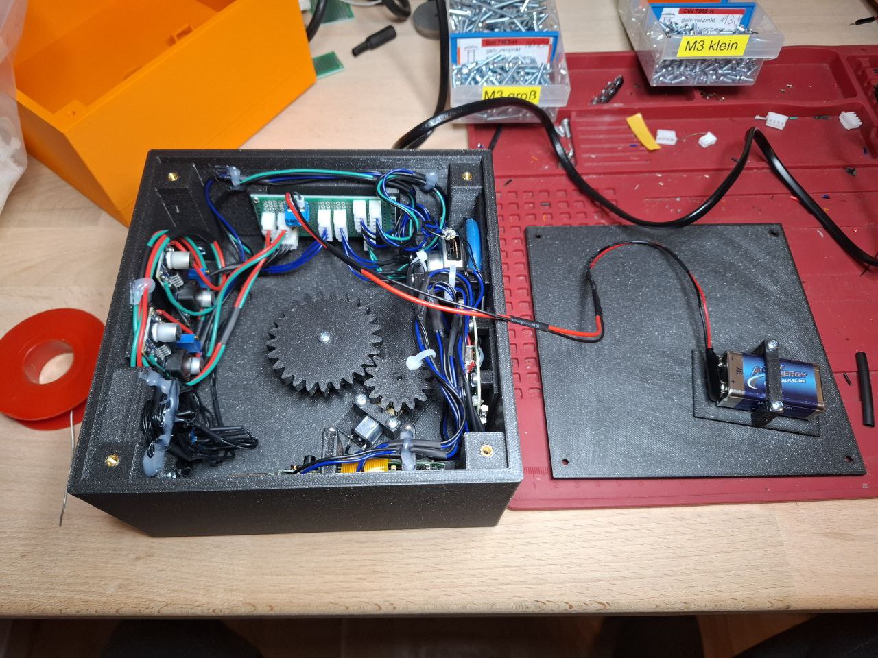
Before it all got glued together it was time for a dry test run.
The 9v battery got mounted on the inside of the lid, for ease of replacement.
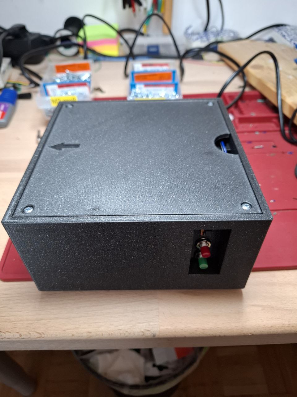
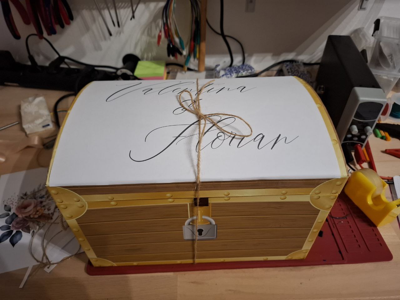
With the lid in place and everything screwed together, it was time for packaging.
Making sure everything stays in place until it will arrive at its destination.
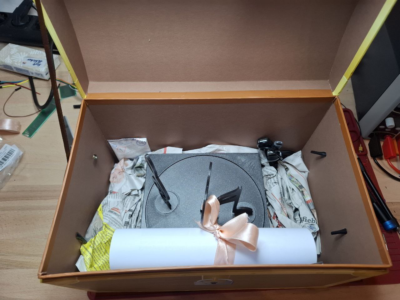
Wish you all the best 💝
Thanks for reading. ~Coni